Welcome to Changzhou kangpani electric motor co. LTD!

+86 18112331965
Free program. Technical support
PRODUCT LINE Products
 scan
scan
Hot-sale products/recommend

040AC servo motor

060AC servo motor

080AC servo motor

110AC servo motor

130AC servo motor

180AC servo motor

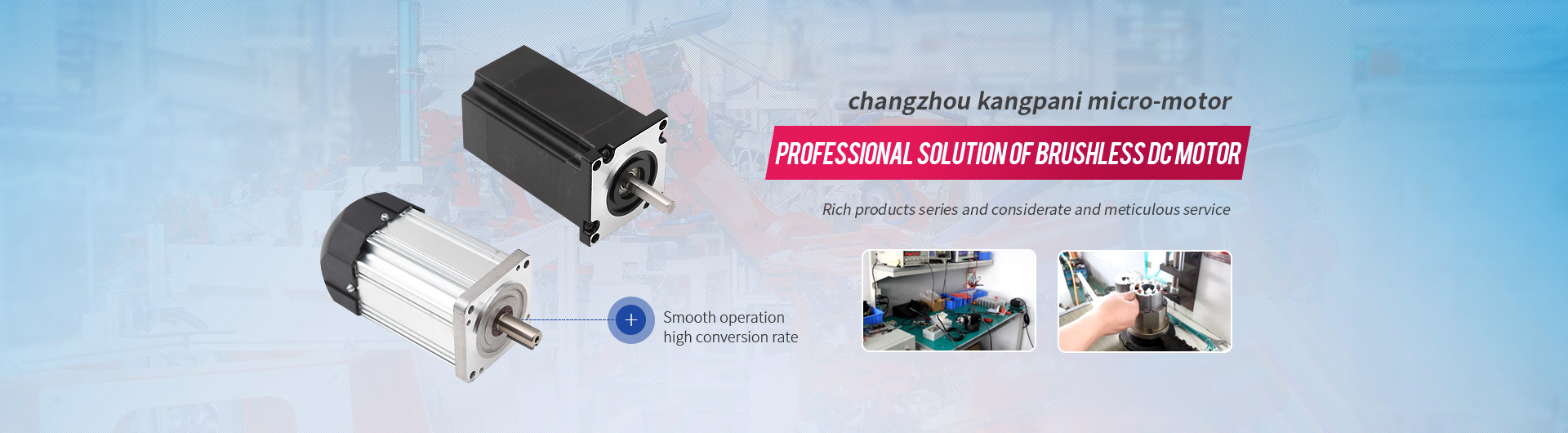
110BL Brushless DC servo motor

110BL Brushless DC motor

86H Stepping brake motor
040AC servo motor
060AC servo motor
080AC servo motor
110AC servo motor
130AC servo motor
180AC servo motor
110BL Brushless DC servo motor
110BL Brushless DC motor
86H Stepping brake motor

86BL Brushless DC servo motor

86BL Brushless DC reduction motor

86BL brushless DC motor

80BF Brushless DC fan motor

80BF brushless DC motor

70BL Brushless DC servo motor

70BL brushless DC motor

60BL Brushless DC servo motor

60BL Brushless DC reduction motor

60BL Brushless DC motor

57BZ Brushless DC reduction motor

57H Stepping brake motor

57BZF brushless DC motor

57BL Brushless DC reduction motor

57BL brushless DC motor

57BZ brushless DC motor

42BZ Brushless DC reduction motor

42BZ brushless DC motor

BLDC4810

BLDC4815

BLDC4830

BLDC22025

BLDC22035

BLDC22050

CPN4806
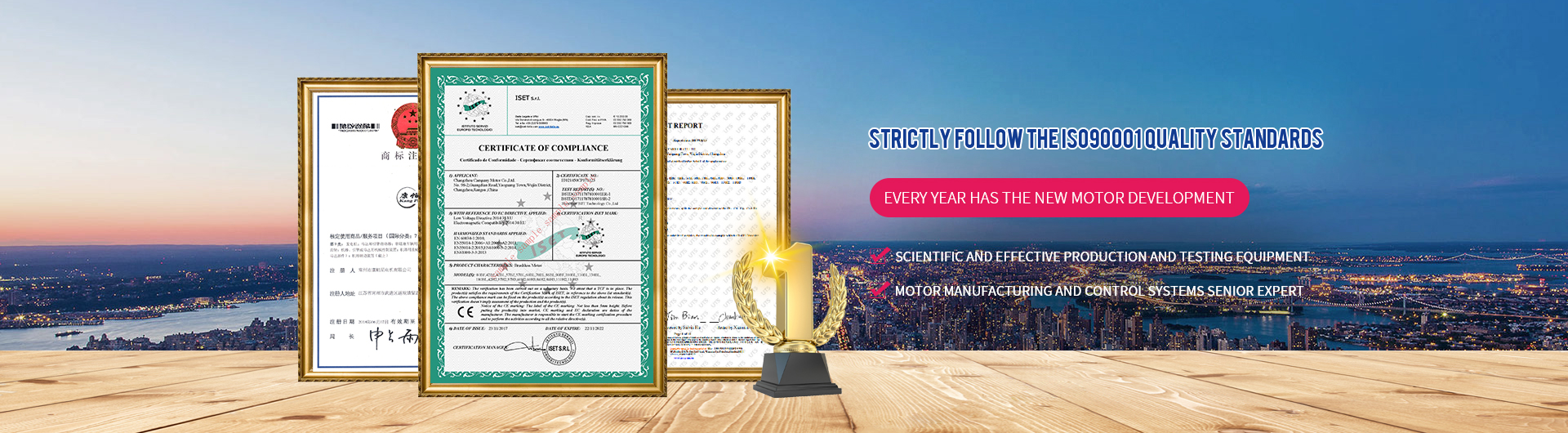
Founded in 2008, it is dedicated to the professional research and production of special micromotor, mainly producing brushless dc motor, servo motor and two-phase and three-phase hybrid stepping motor two series motor products.The company has many electrical, mechanical and electronic engineers, strong technical force, each year there are new varieties of motor development.

The company strictly follows the ISO90001 international quality standard to carry on the quality management and the organization production, the product quality is stable reliable, has the senior electrical machinery manufacture and the control system technical expert, the science effective, the advanced production and the inspection equipment, has the formidable product development ability.

All products sold have independent Numbers, and provide detailed instructions and 24 hours of online consulting services, regular customer satisfaction survey, and timely follow up customer comments.

Industrial robot industry

Automation industry

Unmanned vehicle industry

Industries


High
The heat generated during normal operation of the compressor should not cause overheating.Normal mot...Air conditioning motor: growth hit a six-year high what changes have taken place in the market
SMM network news: looking at the past cold 2017: two words summary "***".Since the beginniWe will strengthen our industrial base
The equipment manufacturing industry is an important part of the country and plays an important roleGrasp the trend to win the future
The development of industries driven by the market and the updating of technology promoted by sciencBrushless dc motor of the next blue ocean: inverter appliances
According to the national policy on energy conservation and environmental protection, the total valu
 Mobile
WeChat
National advisory service hotline:
URL:http://www.cpnmotor.com EMAIL:kpn@kpnmotor.com ADDRESS:4th Floor, Building B3, Hutang Technology Industrial Park, Hutang Town, Wujin District, Changzhou City, Jiangsu Province
A 24-hour hotline 0519-86056070 +86 18112331965
scan QR code
 WhatsApp


