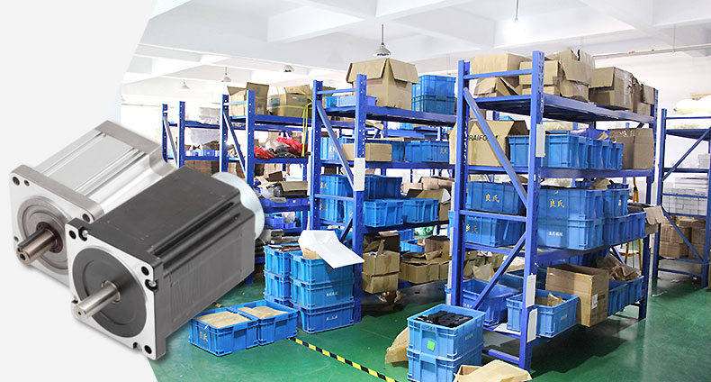
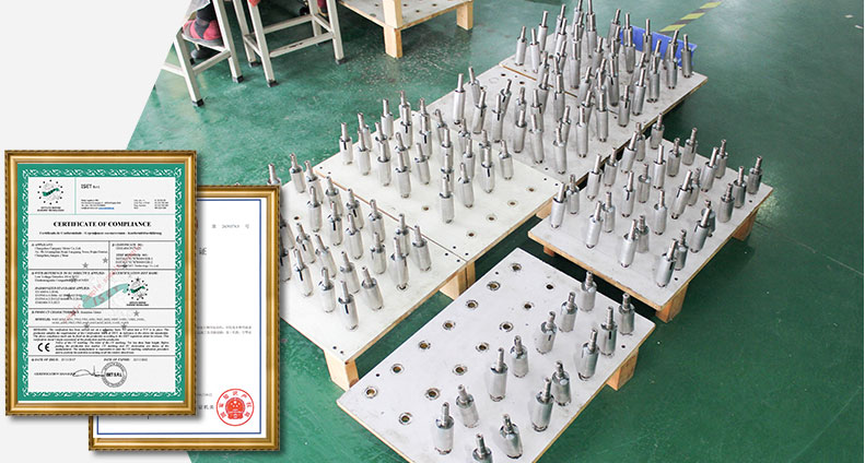
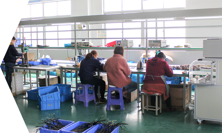
Welcome to Changzhou kangpani electric motor co. LTD!
logo

Special micromotor productionsince 2008

Brushless dc servo motorBrushless dcstepping motor

18151207805 Free program. Technical support
YOUR POSITION : HOME PRODUCT actuator
actuator Brushless DC motor
BLDC22050
keyword : BLDC22050
description : Products are widely used in the field of industrial automation, in addition to a certain domestic market share, but also exported to foreign countries.
18151207805

General Specifications

A summary:

High voltage brushless motor drive is my company independent research and development of high power drives, mainly USES the latest international motor special-purpose DSP as the core digital processor with a high speed digital logic chip high quality power module, component with high integration, small volume, perfect protection, wiring simple, high reliability etc.The driver can provide: operation panel speed setting, external analog voltage speed regulation, external potentiometer speed regulation, pulse width speed regulation and other functions.High-speed core control components control, with safe operation (control components and power components are fully isolated), flexible and diverse speed regulation, speed real-time display, complete protection functions, power components to provide hardware protection and other characteristics.


Product features:

1. System features:

Input power AC220VAC 50/60hz

Continuous output current: 4.9a, suitable for brushless motors below 1200W

Maximum output current: 9.9a,

Use temperature 0 ~ + 45 ° C

Save - 20 ~ + 85 ° C temperature

Use and storage humidity <85% [no frost conditions]

Construction of wall-mounted box type

2. Basic features

Cooling mode: radiator mode

Input and output signals of control letters: fully isolated

Protection machine can: over current, over speed, over voltage, under voltage control power supply abnormal

Panel interface: 6-bit LED display 4-bit key operation

3. Installation precautions

* it is strictly prohibited to open the shell to measure or touch any device and connector on the bottom board during operation.

* check the bottom plate or replace the fuse one minute after power failure.

* it is forbidden to run the drive without shell during operation.

* brushless motor driver and brushless motor shall be well and reliably grounded, otherwise the speed of brushless motor may not be stable.

* if the drive is accidentally damaged during operation, the company is only responsible for the repair and replacement of the drive within the warranty.The company shall not be liable for any loss of control of the motor or loss of life or property caused by accidental damage of the drive.


Ii. Function description of interface terminal

2.1 power and motor terminals

Terminals no.

Terminal symbols

signal name

function

1

L1(L)(R)

Main loop power input

Main circuit power input terminal AC220V 50Hz, when using single-phase 220V should be connected to L1 and L2.

2

L2(N)(S)

3

L3(T)

4

P

High voltage direct current bus head

Drive internal dc bus positive end, rated voltage 315V

5

B1

Internal brake resistance

Short connect B1 and B2 when using internal brake resistors.When the power of the internal brake resistance is insufficient and the external brake resistance is needed, disconnect B1 and B2 and connect the external brake resistance to P and B2.

6

B2

External brake resistance

7

U(MA)

The motor output

Motor output terminals must correspond to the motor U, V and W terminals one by one. Note: do not reverse the motor by switching the three-phase terminals.This is quite different from asynchronous motors.

8

V(MB)

9

W(MC)


PE

protected area

Provide safe drain paths for motor and driver leakage current


Drive size: 180 x 75 x 140 x

图片13 

        CN2端子定义

        8:+5V        +5V电源正极

        7:SV         模拟量输入端(调节速度)

        6:COM        公共端负极

        5:F/R        正、反转控制端

        4:EN         启动/停止

        3:BK         刹车信号控制端

        2:ALM        运行故障报警输出

        1:PG         速度信号输出端


        CN1端子定义:

        5:GND         霍尔电源负极

        4:HA          霍尔A

        3:HB          霍尔B

        2:HC          霍尔C

        1:+5V         霍尔电源正极


Three: parameter setting

3.1Parameter P1

These parameters are used to set up some special custom functions and are usually used for users to adjust the process parameters themselves.The parameters of this part have nothing to do with the basic performance of the driver. They belong to the functional parameters of the application layer and are often adjusted according to the specific operation requirements of users.


name of parameter

Parameter number

Set value range

Factory default

function declaration

Select display content

P1。0

0~9

0


0 displays the current actual motor speed

Display dc bus voltage

Display input value of external analog quantity

Display motor current

4 shows internal planning speed

5 U phase current

6 V phase current

7 W phase current

8 duty ratio

9 keep


Internal running speed

P1。1

0~9999

2000

When the internal speed is selected, the motor speed is determined by this parameter.See P1.2

Select the source of the speed signal

P1。2

0~2

1

0: internal instruction speed (tP1[0] is the internal speed, and MUP and MDOWN keys are used to speed up and decelerate the motor when it moves)

1: external port analog input, using the seventh pin SV signal of CN2 as the motor speed.

2: communication command control


Direction is set

P1。3

0~1

0

0: forward


1: reverse

Select the start - stop signal source

P1。4

0~2

1

0: manual control by pressing the button (ENT key to start and stop, SET key to reverse motor motion direction, +/- key for acceleration and deceleration)


1: external port control, using the fourth pin signal of CN2 to start and stop the motor


2: communication command control

Motor pole logarithm

P1。5

0~99

2

Motor pole logarithm,


Note: motor pole number = motor pole number /2

驱动器地址

P1。6

0~255

0

使用通讯控制电机时驱动器的地址

速度比例因子

P1。7

0~99999

1520

用于PID速度控制中的比例因子KP

速度积分因子

P1。8

0~99999

320

用于PID速度控制中的积分因子KI

电机加速度

P1。9

1~60000

6000

该参数和加速度成正比,获得的电机实际加速度和负载及电机等情况有关。

电机减速度

P1。10

1~60000

6000

电机额定速度设定

P1。11

0~99999

3000

单位转/分钟(RPM)当模拟量输入为最大值时所对应的电机转速。

模拟输入死区电压

P1。12

0~3300

100

单位毫伏,该参数用于设置电机零速度时对应的输入电压。

手动速度调节当量

P1。13

1~999

1

内部速度模式时用按键改变速度的当量(按1下按键增减的转速)

恢复默认参数

P1。14

0~1

0

设为1并退出设置,重新上电,所有参数都会恢复为默认值


3.2面板操作方法


图片14

As shown on the left, there are four buttons on the panel, respectively

"SET" : "SET". Press this key to enter and exit the setting menu of P1 series.

"" and" ":" add "and" subtract "are respectively used to select the parameter number and adjust the parameter value, wherein" add "is the hot key to enter the test operation function.

"ENT" : "confirm" and "run". When setting parameters, the function of this key is to enter the parameter value adjustment interface and jump bits.In test run mode, this key is used to start and stop the motor operation.

Display description: a total of six digital tube display "888888", the most right is the first, is the lowest.

Note: if the value of the parameter you are trying to modify is greater than the maximum allowed value of the parameter, the change will not be allowed and the button will not respond.

3.3 how to set parameters

Examples:

Requirements: set internal speed (P1.1) to 1000 RPM.

The operation steps are as follows:

1.After power on, "H 0" is displayed, and the drive is in standby state. Press "SET".

Displays "P0.0 ".

2.Press the "SET" key to display "P1".0 ", the driver enters the setting state state of parameter P1.

Press the ' 'button until' P1 'appears.4 ".

4. Press "ENT" to display "2000", and the first digit on the far right flashes.

5. Press "ENT" key and the flicker bit moves forward to the 4th bit.

The 1000 setting is given by pressing the button.

7. Press "SET" to display "P1".4 ", parameter modification is completed and automatically saved.

8. Press "SET" again to display "P2 0".

9. Press "SET" key again to return to the standby state and display "H 0". At this point, the parameter modification is completed and the new parameter takes effect.

Note: after some parameters are modified, they cannot take effect until they are powered on again.

Note: the name marked with in the parameter table indicates that this parameter cannot be modified when the motor is running.

Note: if the value of the parameter you are trying to modify is greater than the maximum allowed value of the parameter, the change will not be allowed and the button will not respond.

图片15

Function and use

(1) speed regulation

The driver provides the following three speed regulation modes:

Analog voltage regulating external potentiometer can be two fixed end joint respectively in the drive control signal port of + 5 v and COM, will adjust the termination in the SV side can use an external potentiometer (10 k ~ 100 k) speed regulation, can also be controlled by other units (such as PLC, SCM, etc.) to the input analog voltage SV server-side implementation speed (relative to the COM), SV port to accept in the range of DC 0 v ~ + 5 v, corresponding to the motor speed of 0 ~ rated speed.

Can also use external digital signal speed regulation: between SV and GND can be applied to the amplitude of 5V, frequency of 1KHz~2KHz pulse width digital signal (PWM) for speed regulation, motor speed by its duty cycle linear regulation.

This driver can also adopt communication mode control.

(2) motor operation/stop control (EN)

The operation and stopping of the motor can be controlled by the on-off of the control terminal EN relative to COM.When connected with the terminal, the motor will stop.When the running/stopping end is used to control the motor to stop, the motor starts and stops according to the starting time set by the panel, and its motion law is affected by the load inertia.

(3) motor forward/reverse control (F/R)

The running direction of the motor can be controlled by controlling the on-off of terminal F/R and terminal COM.When F/R is not connected with the terminal COM, the motor will run clockwise (facing the motor shaft), otherwise, the motor will run counterclockwise: when the motor is in the running state for forward/reverse selection and switching, the motor will automatically stop and then start the operation in the opposite direction.

Brake (BR)

The brake stop of the motor can be controlled by controlling the on-off of terminal BR and terminal COM.When the control terminal BK is disconnected from the terminal COM, the motor will run and stop when the motor is connected. In case of frequent overvoltage alarm in the drive, the brushless drive shall be equipped with brake resistance, with recommended resistance value of no less than 100 ohms and power of no less than 100W. During installation, the drive must be in the state of power off and the indicator light off.Additional brake resistance is optional and will be charged separately.

(5) motor speed signal output (PG)

Speed pulse output, the port is OC output (30V/10mA Max).PG end with the power of the indirect 3 k Ω ~ 10 k Ω pull-up resistor.The relationship between the output frequency F (HZ) and the motor speed N(RPM) is as follows: F=N * P / 60, where P is the number of motor poles, that is, the pulse output per revolution of the motor is the number of poles of the motor.

(6) alarm output

Driver alarm output, the port is OC output (30V/10mA Max).Alarm output end and the power of the indirect 3 k Ω ~ 10 k Ω pull-up resistor.When alarming, this terminal conducts with GND (low level), and at the same time, the driver stops working by itself and is in the alarming state.

4.2 working mode:

There are three working modes of the driver, which can be set by the panel.Second is the external port working mode;Motor in accordance with the setting mode, digital tube display motor speed.In the working mode of the panel, press R/S key to start and stop the motor, long press + and - keys to increase and decrease the motor speed, and press given ENTER key to determine the motor speed.The motor runs at the set speed.The third is communication.

4.3 protection mode:

When the motor in the process of operation, abnormal, digital tube display.

(1) OL means the motor is blocked.

(2) OC stands for over current.

(3) HE means hall fault.

(4) LV represents input undervoltage.

(5) HU means input overvoltage.

(6) EE means IPM module fault protection.

(7) OT means motor overheating.

V. system usage:

Firstly, connect the connection line (motor winding line, hall signal line and power line) between the motor and the driver, and the connection line must be strictly in accordance with the requirements. Unlike asynchronous motor, positive and negative rotation can not be realized by changing the connection line. Incorrect connection will lead to the motor not running, or abnormal operation, which may damage the motor and the driver.

When the motor power of wires, HALL and connect the power cord drive, can, to set up the motor control panel control or port control, and then set the brushless motor of logarithmic (incorrect polar logarithmic display speed, and the internal parameters call errors), and then press start switch, potentiometer slightly increase motor, the motor should be run, such as the motor is not running, or shiver, or device alarm, the possibility of electrical wiring is wrong or the external load is too big, please check again brushless motor and external load, and can realize the normal movement of the motor, stop.

Other products


Foreign technology imported materials precision manufacturing Introduction of foreign technology, kompany electric power conversion rate, more energy saving
  • 噪音小
    Low noise
  • 运转平稳
    smooth
  • 高效精准
    accurate
  • 安全耐用
    durable

Product types choosing

Submit your requirements

Free access to electrical experts to provide you with project solutions
Enquiry hotline 18151207805
Changzhou kangpani electric motor co. LTD
Stepping brake motor brushless DC motor Brushless DC reduction motor Brushless DC fan motor actuator

A 24-hour hotline 0519-86056070 18151207805

Changzhou kangpani electric motor co. LTD scan QR code

Online Message