An overview,
This series actuators for closed loop speed controller, use the recent type IGBT and power MOS device, using brushless dc motor of hall signal after the frequency doubling of closed loop speed control, control link is equipped with PID speed regulator, stability and reliability of the control of the system, especially at low speeds can always achieve maximum torque, speed control range of 150 ~ 20000 RPM.
Second, the characteristics of
1, PID speed, current double loop regulator
2. Compatible with or without hall, automatic identification, non-inductive mode is only suitable for special occasions (start-up load is relatively constant)
3. High performance and low price
4. 20KHZ chopper frequency
5, electric brake function, make the motor response quickly
6. The overload multiple is greater than 2, and the torque can always reach the maximum at low speed
7, with over voltage, under voltage, over current, over temperature, hall signal illegal fault alarm function
Electrical indicators
Recommended standard input voltage: 24VDC~48VDC, under voltage protection point 8VDC, overvoltage protection point 60VDC.
Maximum continuous input overload protection current: 15A, factory default set to 10A.
Acceleration time constant factory value: 0.5 seconds other customizable
Safety precautions
This product belongs to professional electrical equipment and should be installed, debugged, operated and maintained by professional technicians.Improper use will lead to electric shock, fire, explosion and other dangers.
This product is powered by dc power supply. Please confirm that the positive and negative poles of the power supply are correct before powering up
Do not plug or unplug the connecting cable while it is live, and there is no short connection of the cable in the power on, otherwise it will cause damage to the product
If the motor needs to change direction during operation, the motor must be slowed down to stop before reversing
The drive is not sealed, please do not mix screws, metal chips and other conductive or combustible foreign body inside, please pay attention to moisture and dust when storage and use
Drive for power equipment, as far as possible to maintain the working environment of heat and ventilation
The warranty limits
Product warranty coverage is limited to the components and process (i.e., consistency) of the product.
The company does not guarantee that its products can be suitable for the specific use of the customer, because the suitability of the use is also related to the technical index requirements and the use conditions and environment.
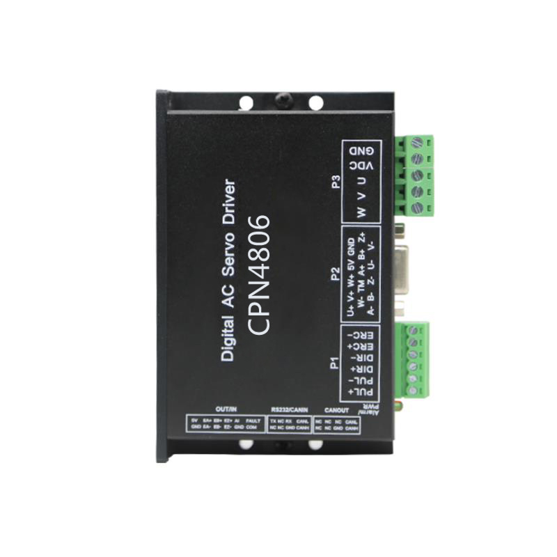
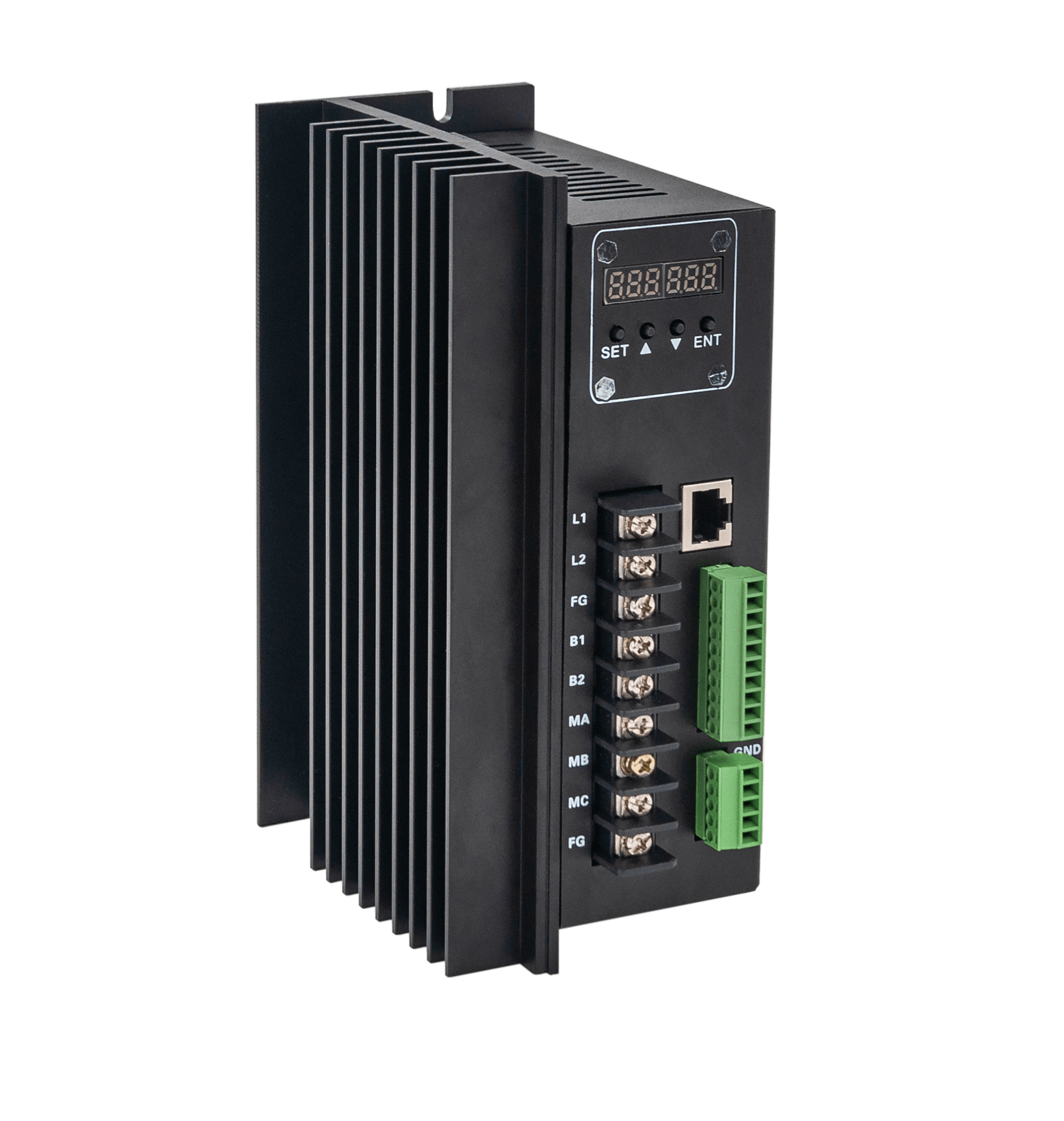
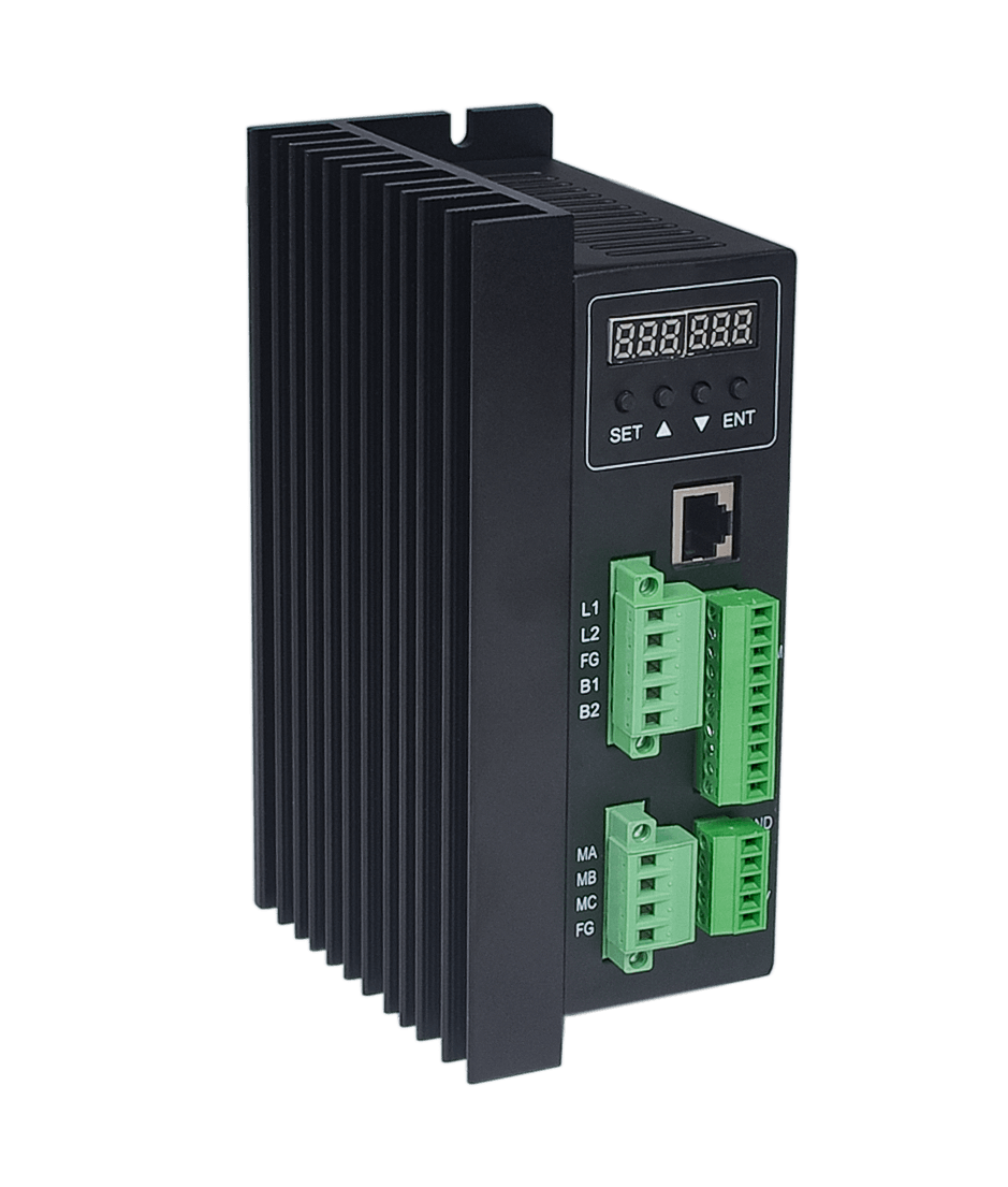
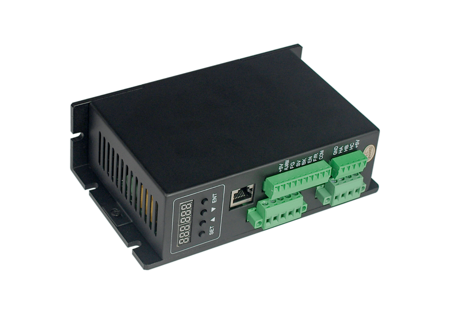
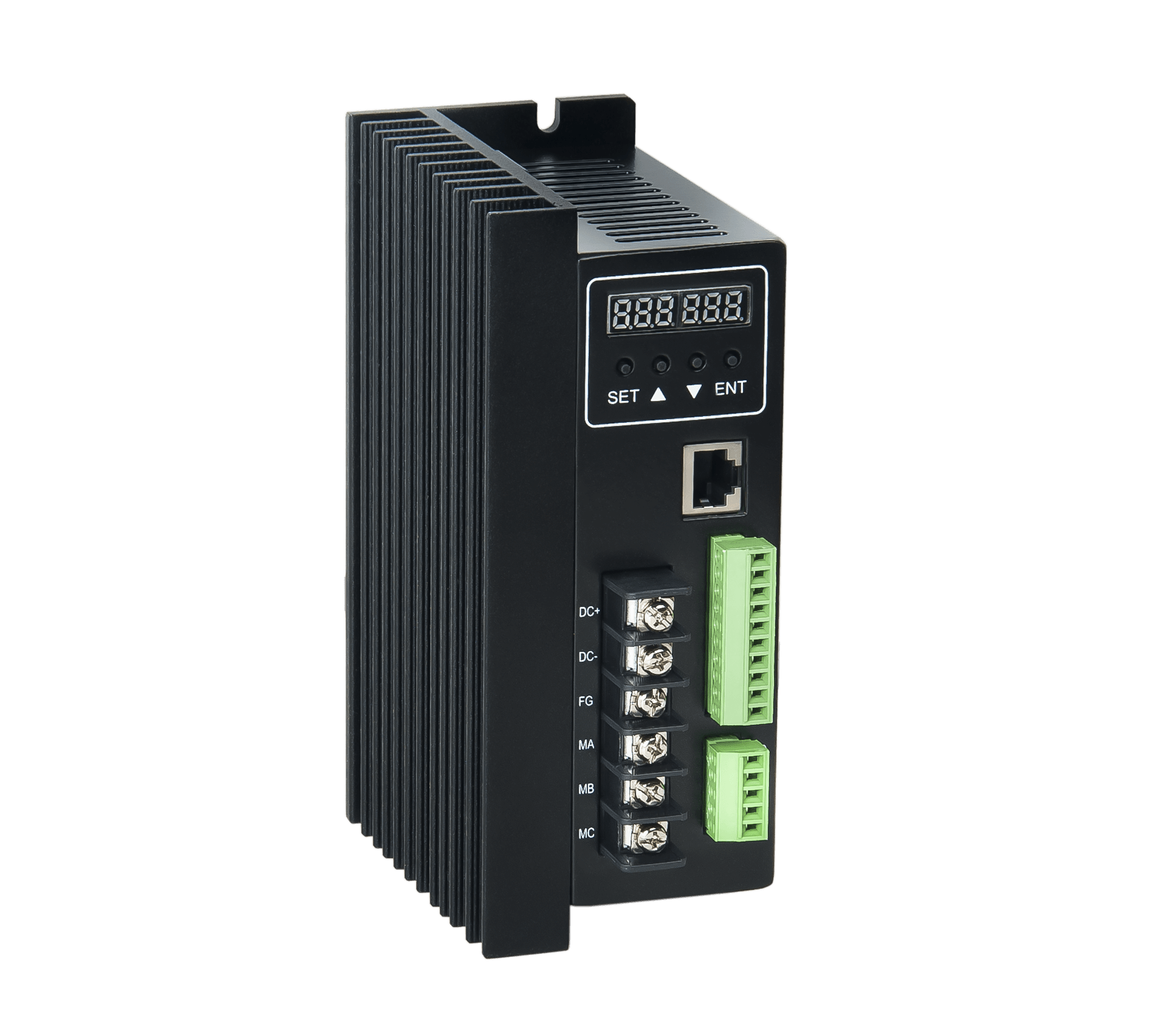
Iv. Description of terminal interface
1. Power input terminal
Lead Angle of the serial number | Lead Angle name | Chinese definition |
| 1 | V+ | Dc positive input (+24-48v) |
| 2 | GND | Dc negative input |
2. Motor input terminal
Lead Angle of the serial number | Lead Angle name | Chinese definition |
| 1 | MA | A motor phase |
| 2 | MB | B motor phase |
| 3 | MC | C motor phase |
| 4 | GND | ground electrode |
| 5 | HA | Hall signal A phase input terminal |
| 6 | HB | Hall signal B phase input terminal |
| 7 | HC | Hall signal C phase input terminal |
| 8 | +5v | The power end of the hall signal |
3. Control signal part
GND: signal ground
F/R: forward and reverse control, connected to GND reverse, not connected to forward
EN: enable control;EN ground, motor running (on-line), EN not connected, motor not running (offline)
BK: brake control;When ungrounded works normally, when grounded, the motor brakes electrically.
SV: analog 0-5vdc input, control motor speed 0~ set speed.
PG: motor speed pulse output;When the polar logarithm is P, 3P pulses are output per revolution (OC gate input).
ALM: alarm output;When the circuit is in alarm state, output low level (OC gate output)
+5V: speed regulation voltage output, available potentiometer in SV and GND forming continuous adjustable
Communication port: RS485 dual wire serial link communication, communication connection control or computer connection to modify parameters.
Built-in potentiometer r-sl: adjust the motor speed gain from 0 to 100%.The maximum speed set by the factory is 14000r/min for the brushless single pair motor, 7000r/min for the 2 pairs, 3500r/min for the 4 pairs and 1750r/min for the 8 pairs.
Built-in potentiometer r-cs: set the maximum protection current, and the potentiometer can set 0%~100% continuous current protection
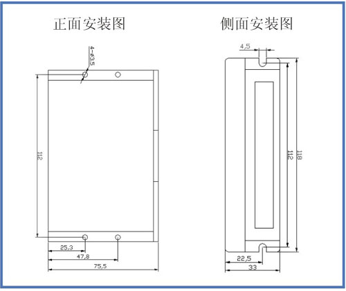
4. Mechanical installation:
V. function and use
Speed way
The driver provides the following three speed regulation modes:
Internal potentiometer speed regulation: rotate the potentiometer motor speed on the driver panel counterclockwise to reduce, clockwise to increase the speed.When the user USES the external input speed regulation must set the potentiometer in the minimum state.
External input speed will be an external potentiometer two fixed end connect to the GND and + 5 v end of the drive, will adjust the termination in the SV side can use an external potentiometer (10 k ~ 50 k) speed regulation, can also be controlled by other units (such as PLC, SCM, etc.) input analog voltage to the SV to achieve speed control (relative to the GND), SV port to accept in the range of DC OV ~ + 5 v, corresponding to the motor speed of 0 ~ rated speed.
Can also use external digital signal speed regulation: between SV and GND can be applied to the amplitude of 5V, frequency of 1KHz~2KHz pulse width digital signal (PWM) for speed regulation, motor speed by its duty cycle linear regulation.At this time, the amplitude of SV digital signal can be attenuated by 0-1.0 ratio by adjusting r-si potentiometer. Generally, the r-si is adjusted to 1.0, and the SV input digital signal is not attenuated.
The motor speed can also be changed by means of communication with instructions.
Motor operation/stop control (EN)
The on and off of the control terminal EN relative to GND can control the operation and stop of the motor.When the terminal is disconnected, the motor will stop.When the running/stopping end is used to control the motor to stop, the motor will stop naturally, and its motion law is related to the load inertia.
Motor forward/reverse control (F/R)
By controlling the on and off of terminal F/R and terminal GND, the running direction of the motor can be controlled.When F/R and terminal GND are not connected, the motor will run clockwise (facing the motor shaft), otherwise, the motor will run counterclockwise.In order to avoid the damage of the driver, when changing the motor steering, the motor should be stopped before changing the steering to avoid operating in the direction of the motor operation.
Brake stop
By controlling the on and off of terminal BK and terminal GND, the motor's braking and stopping can be controlled.When the control terminal BK is disconnected from the terminal GND, the motor runs, and when the motor is connected, the quick braking stops, and the braking shutdown is faster than the natural shutdown. The specific shutdown time is related to the load inertia of the user system.If there is no special stop requirement, natural stop should be adopted because the stop of braking has impact on electrical and machinery.
Motor speed signal output (PG)
The speed pulse output, the port for OC output (30 v / 10 ma Max), to get a signal with the power of the indirect 3 k Ω ~ 10 k Ω pull-up resistor.The number of output pulses per revolution of the motor is 3 x N, and N is the polar logarithm of the motor.Example: the 2-pole, or quadrupole, motor has 6 pulses per revolution.When the motor speed is 500 RPM, the output pulse of terminal PG is 3000.
Alarm output
Driver alarm output, the port is OC output (30V/10mA Max).To get a signal with the power of the indirect 3 k Ω ~ 10 k Ω pull-up resistor.When alarming, this terminal conducts with GND (low level), and at the same time, the driver stops working by itself and is in the alarming state.
Driver failure
Drive internal failure, such as over-voltage or over-current protection drive into the state, the drive will automatically stop working, the motor stops, the driver on the red light is flashing, flashing number corresponding to different fault phenomenon, as long as will make the end to reset (that is, EN and GND disconnect) or power, drive will lift the alarm.In case of this fault, please check the motor wiring or remove the load.
Red light flashes once: excessive current alarm
Red light flashes twice: hall motor fault
The red light flashes three times: power undervoltage alarm
Red light flashing four times: power overvoltage alarm
Red light flashing five times: motor peak current alarm
Red light flashing six times: motor block alarm
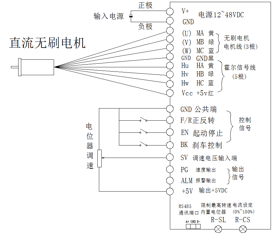
Wiring diagram of driver and brushless motor
Vi. Communication:
The communication mode adopts standard Modbus protocol and conforms to national standard GB/T 19582.1 -- 2008.Using RS485 based double wire serial link communication, the physical interface USES the conventional 3-pin wiring port (A+,GND,B-), the serial connection is very convenient.
If the driver control needs to adopt the communication mode, the control mode of the driver needs to be changed. The default mode is the external analog speed regulation mode, which is changed to the communication mode control. It needs to connect the computer through the RS485 to the USB port, and modify the tool program through the motor controller setting.Specific communication instructions and sample routines are available through the sales engineer.