An overview,
This type control drive for closed loop speed controller, adopts the newest IGBT and power MOS device, using brushless dc motor of hall signal after the frequency doubling of closed loop speed control, control link is equipped with PID speed regulator, stability and reliability of the control of the system, especially at low speeds can always achieve maximum torque, speed control range of 150 ~ 10000 RPM.
Second, the characteristics of
1, PID speed, current double loop regulator
2. High performance and low price
3. 20KHZ chopper frequency
4, electric brake function, make the motor response quickly
5. The overload multiple is greater than 2, and the torque can always reach the maximum at low speed
6, with over voltage, under voltage, over current, over temperature, hall signal illegal fault alarm function
7. Compatible with holeless drive, it can be used as a brushless holeless drive alone
Electrical indicators
Standard input voltage: 24VDC~48VDC, minimum voltage 12VDC, maximum voltage 70VDC.
Maximum input overload protection current: 30A
Maximum continuous output current: 15A
Factory value of acceleration time constant: 0.2 seconds
Motor blocking protection time 5 seconds, other customizable
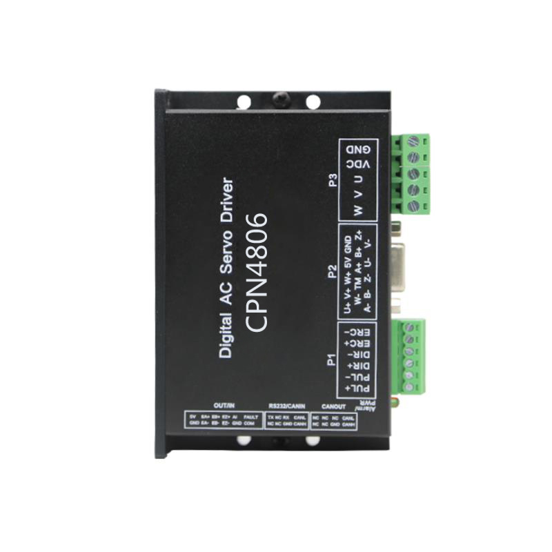
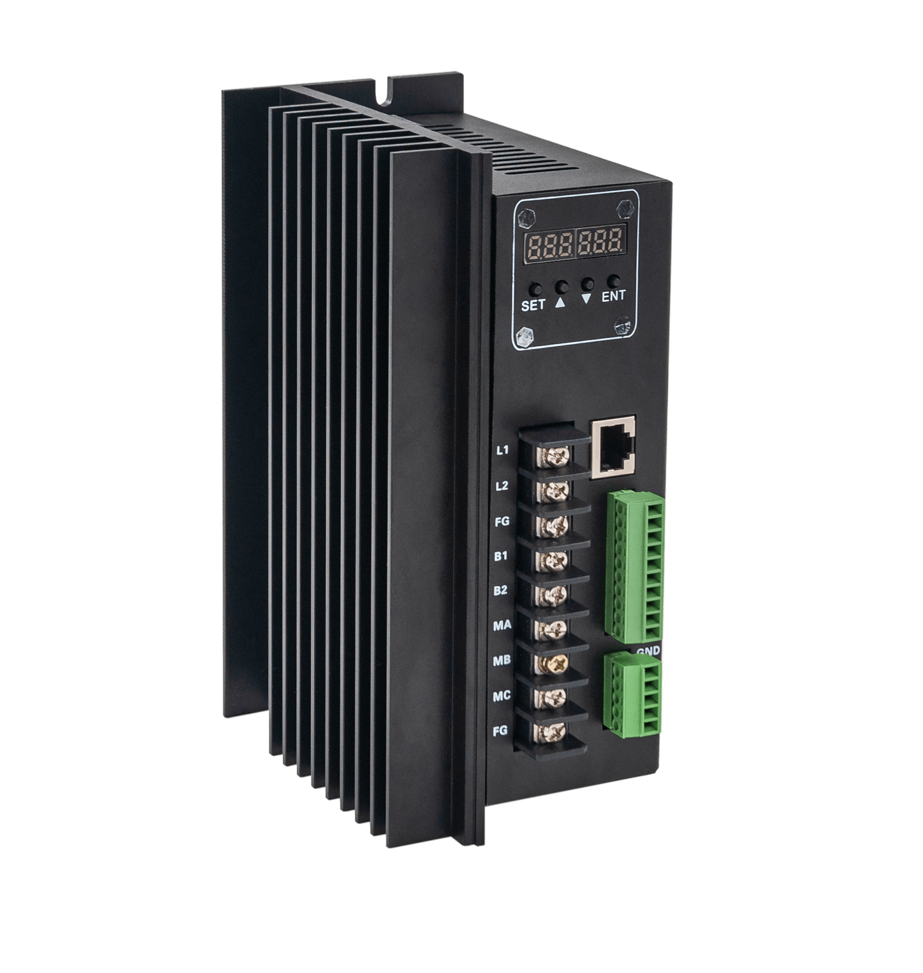
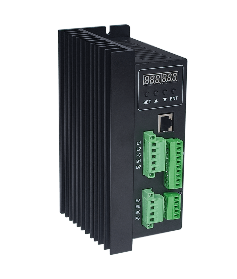
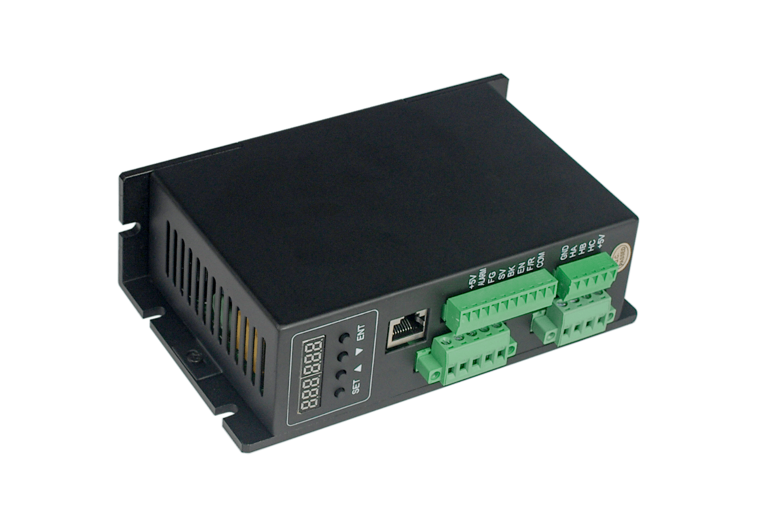
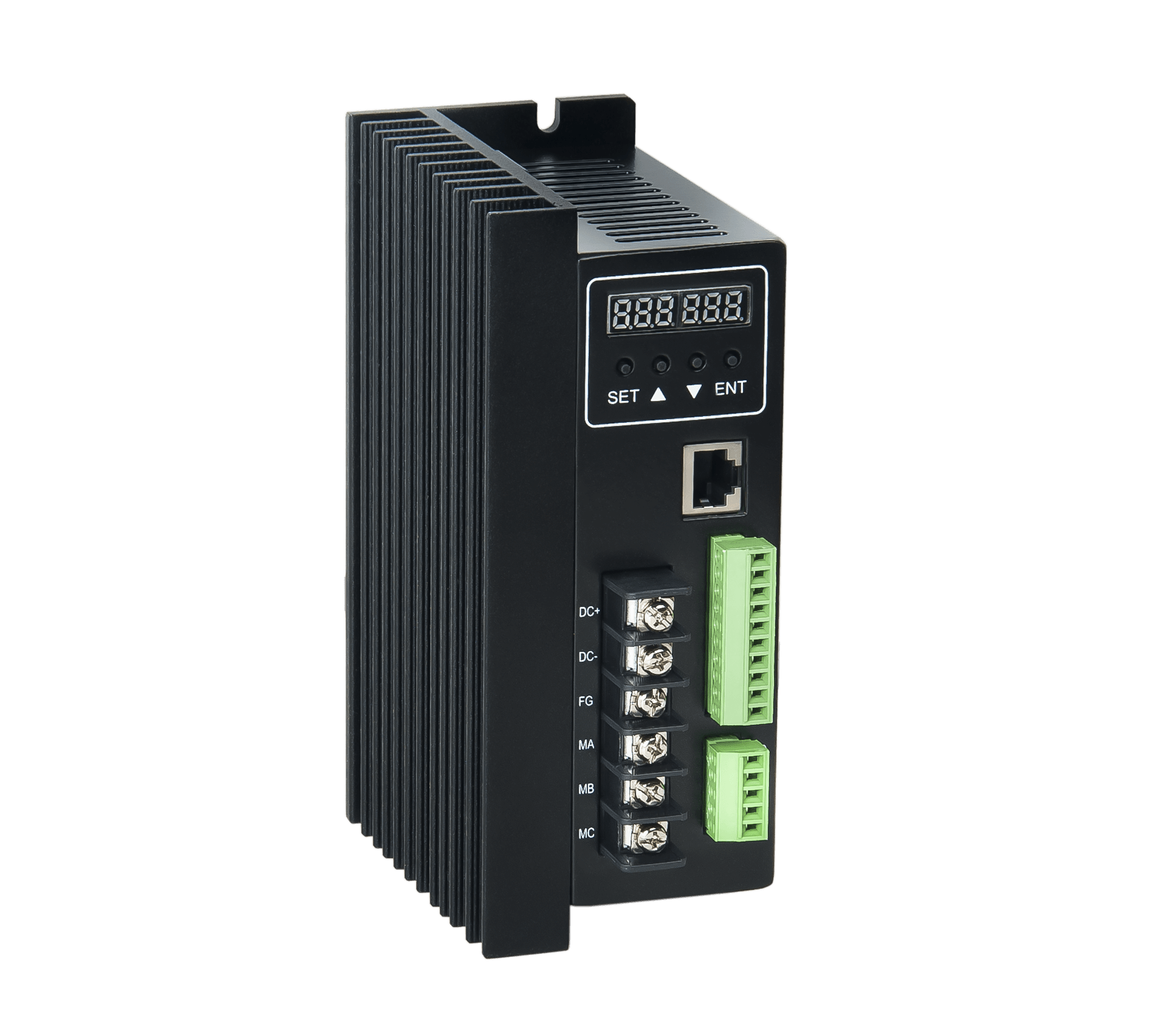
Iv. Description of terminal interface
1. Power input terminal
Lead Angle of the serial number | Lead Angle name | Chinese definition |
| 1 | V+ | Dc +24~48VDC input |
| 2 | GND | GND input |
2. Motor input
Lead Angle of the serial number | Lead Angle name | Chinese definition |
| 1 | MA | A motor phase |
| 2 | MB | Motor phase B |
| 3 | MC | Motor phase C |
| 4 | GND | ground electrode |
| 5 | HA | Hall signal A phase input terminal |
| 6 | HB | Hall signal B phase input terminal |
| 7 | HC | Hall signal C phase input terminal |
| 8 | +5V | The power cord for hall's signal |
3. Control signal part
GND: signal ground
F/R: forward and reverse control, connected with GND reversal, not connected with forward rotation, when switching between positive and reverse, EN should be closed first
EN: enable control: EN ground, motor turn (on line), EN not connected, motor not turn (off line)
BK: brake control: when ungrounded, it works normally. When grounded, the electrical motor brakes. When the load inertia is large, the pulse width signal should be adopted to control the braking effect by adjusting the pulse width value.
SV analog voltage input terminal: can attenuate from 0 to 100%, when the external speed instruction connected to 0~5V, through this port can speed trial
PG: motor speed pulse output: when the number of poles is P, P pulses are output per revolution (OC gate input)
ALM: alarm output: when the circuit is in the alarm state, the output low level (OC gate output)
+5V: speed regulation voltage output, available potentiometer in SV and GND forming continuous adjustable
Built-in potentiometer: adjust the speed gain of the motor, which can be adjusted from 0 to 100%.
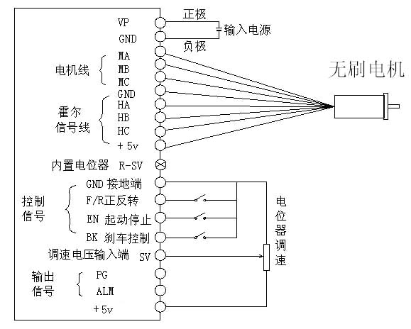
Wiring diagram of driver and brushless motor
Iv. Mechanical installation:

V. function and use
Speed way
The driver provides the following two speed regulation modes:
Internal potentiometer speed regulation: rotate the potentiometer motor speed on the driver panel counterclockwise to reduce, clockwise to increase the speed.When the user USES the external input speed regulation must set the potentiometer in the minimum state.
External input speed will be an external potentiometer two fixed end connect to the GND and + 5 v end of the drive, will adjust the termination in the SV side can use an external potentiometer (5 k to 100 k) speed regulation, can also be controlled by other units (such as PLC, SCM, etc.) input analog voltage to the SV to achieve speed control (relative to the GND), SV port to accept in the range of DC OV ~ + 5 v, corresponding to the motor speed of 0 ~ rated speed.
Can also use external digital signal speed regulation: between SV and GND can be applied to the amplitude of 5V, frequency of 1KHz~2KHz pulse width digital signal (PWM) for speed regulation, motor speed by its duty cycle linear regulation.At this time, the amplitude of SV digital signal can be attenuated by 0-1.0 ratio by adjusting r-sv potentiometer. Generally, the r-sv is adjusted to 1.0, and the input digital signal of SV is not attenuated.
Motor operation/stop control (EN)
The on and off of the control terminal EN relative to GND can control the operation and stop of the motor.When the terminal is disconnected, the motor will stop.When the running/stopping end is used to control the motor to stop, the motor will stop naturally, and its motion law is related to the load inertia.
Motor forward/reverse control (F/R)
By controlling the on and off of terminal F/R and terminal GND, the running direction of the motor can be controlled.When F/R and terminal GND are not connected, the motor will run clockwise (facing the motor shaft), otherwise, the motor will run counterclockwise.In order to avoid the damage of the driver, when changing the motor steering, the motor should be stopped before changing the steering to avoid operating in the direction of the motor operation.
Brake stop
By controlling the on and off of terminal BK and terminal GND, the motor's braking and stopping can be controlled.When the control terminal BK is disconnected from the terminal GND, the motor runs, and when the motor is connected, the quick braking stops, and the braking shutdown is faster than the natural shutdown. The specific shutdown time is related to the load inertia of the user system.If there is no special stop requirement, natural stop should be adopted because the stop of braking has impact on electrical and machinery.
Motor speed signal output (PG)
The speed pulse output, the port for OC output (30 v / 10 ma Max), to get a signal with the power of the indirect 3 k Ω ~ 10 k Ω pull-up resistor.The terminal will output frequency and motor speed is proportional to the fixed pulse width (50uS) negative pulse string, motor per revolution of the output pulse number of 3 x N, N is the number of motor poles.Example: the 2-pole, or quadrupole, motor has 6 pulses per revolution.When the motor speed is 500 RPM, the output pulse of terminal PG is 3000.
Alarm output
Driver alarm output, the port is OC output (30V/10mA Max).To get a signal with the power of the indirect 3 k Ω ~ 10 k Ω pull-up resistor.When alarming, this terminal conducts with GND (low level), and at the same time, the driver stops working by itself and is in the alarming state.
Driver failure
The drive will automatically stop working and the motor will stop. The blue light on the drive is flashing. As long as the enabling end is reset (that is, EN is disconnected from GND) or the power is cut off, the drive can remove the alarm.Please check the motor wiring in case of this fault.
Six, the driver use step
1. Correctly connect the motor wire, hall wire and power line.Incorrect wiring can cause motor and drive damage.
2. When using the built-in potentiometer for speed regulation, connect EN to GND signal ground, connect SV port to +5V, and adjust the speed with the built-in potentiometer r-sv.
3. If the external potentiometer is used for speed regulation, adjust r-sv to the position of 1.0, ground EN at the same time, connect the moving point (intermediate interface) of the external potentiometer to driver SV port, and connect the other two to GND and +5V ports.
4. Power on. At this time, the motor is in the highest closed loop state, and adjust the attenuation potentiometer to the required speed.