I. overview:
This driver is our company to cooperate with the modern industrial automatic control field and the independent research and development of small power driver, mainly USES the foreign high-performance special brushless dc motor driver chip, the composition has a high degree of integration, small size, perfect protection, simple wiring, high reliability a series of advantages.The actuator is suitable for driving small and medium brushless dc motors with rated power up to 750W.This driver adopts the new PWM technology, which makes the brushless motor run faster, vibrate less, noise less, stable and reliable.
Ii. Product features
1. System features:
Input power supply 24VDC ~ 48VDC, maximum continuous current 30A, voltage range 10-60vdc, recommended power does not exceed 750W.
Use temperature 0 ~ + 45 ° C
Save - 20 ~ + 85 ° C temperature
Use and storage humidity <85% [no frost conditions]
Construction of wall-mounted box type
2. Basic features
Cooling mode: radiator mode
Input and output signals of control letters: fully isolated
Protection machine can: over current, over heat, over voltage, under voltage control, abnormal power supply
3. Installation precautions
* it is strictly prohibited to open the shell to measure or touch any device and connector on the bottom board during operation.
* check the bottom plate or replace the fuse one minute after power failure.
* it is forbidden to run the drive without shell during operation.
* brushless motor driver and brushless motor shall be well and reliably grounded, otherwise the speed of brushless motor may not be stable.
* if the drive is accidentally damaged during operation, the company is only responsible for the repair and replacement of the drive within the warranty.The company shall not be liable for any loss of control of the motor or loss of life or property caused by accidental damage of the drive.
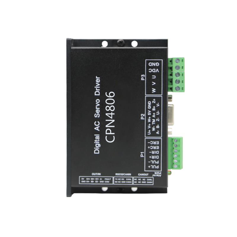
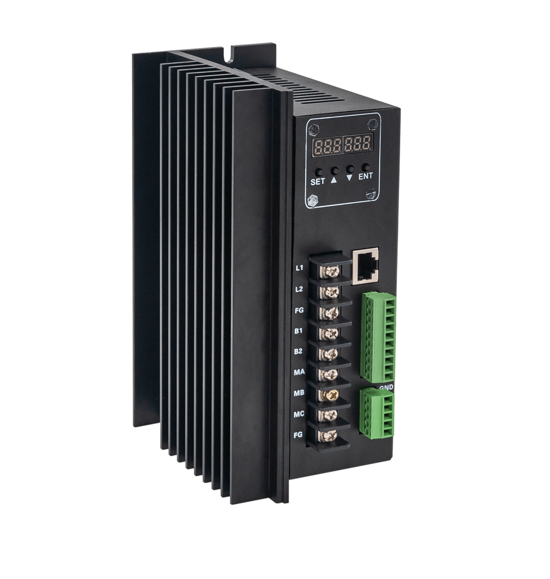
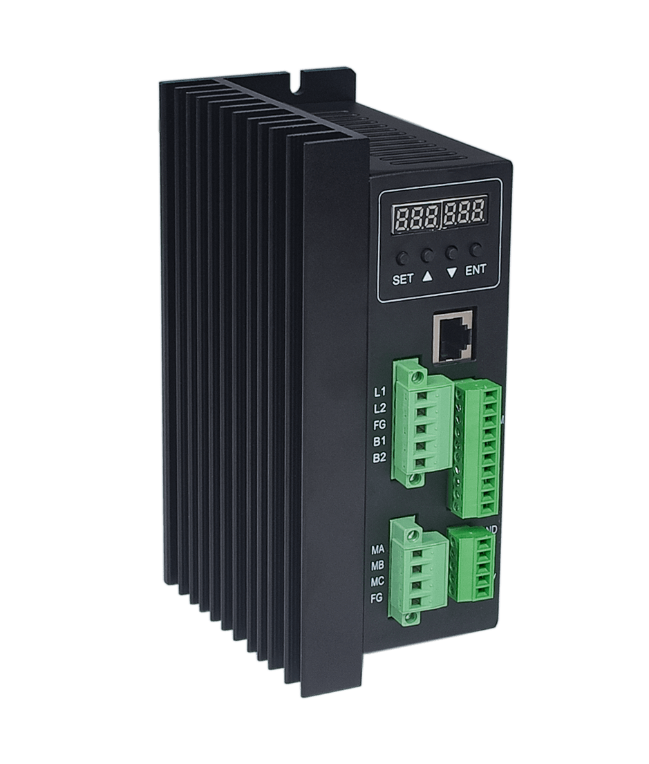
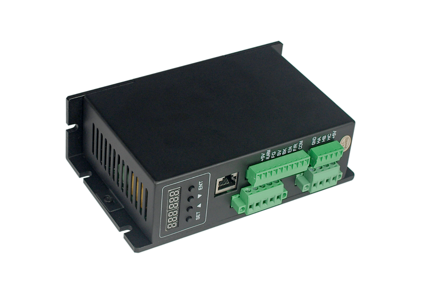
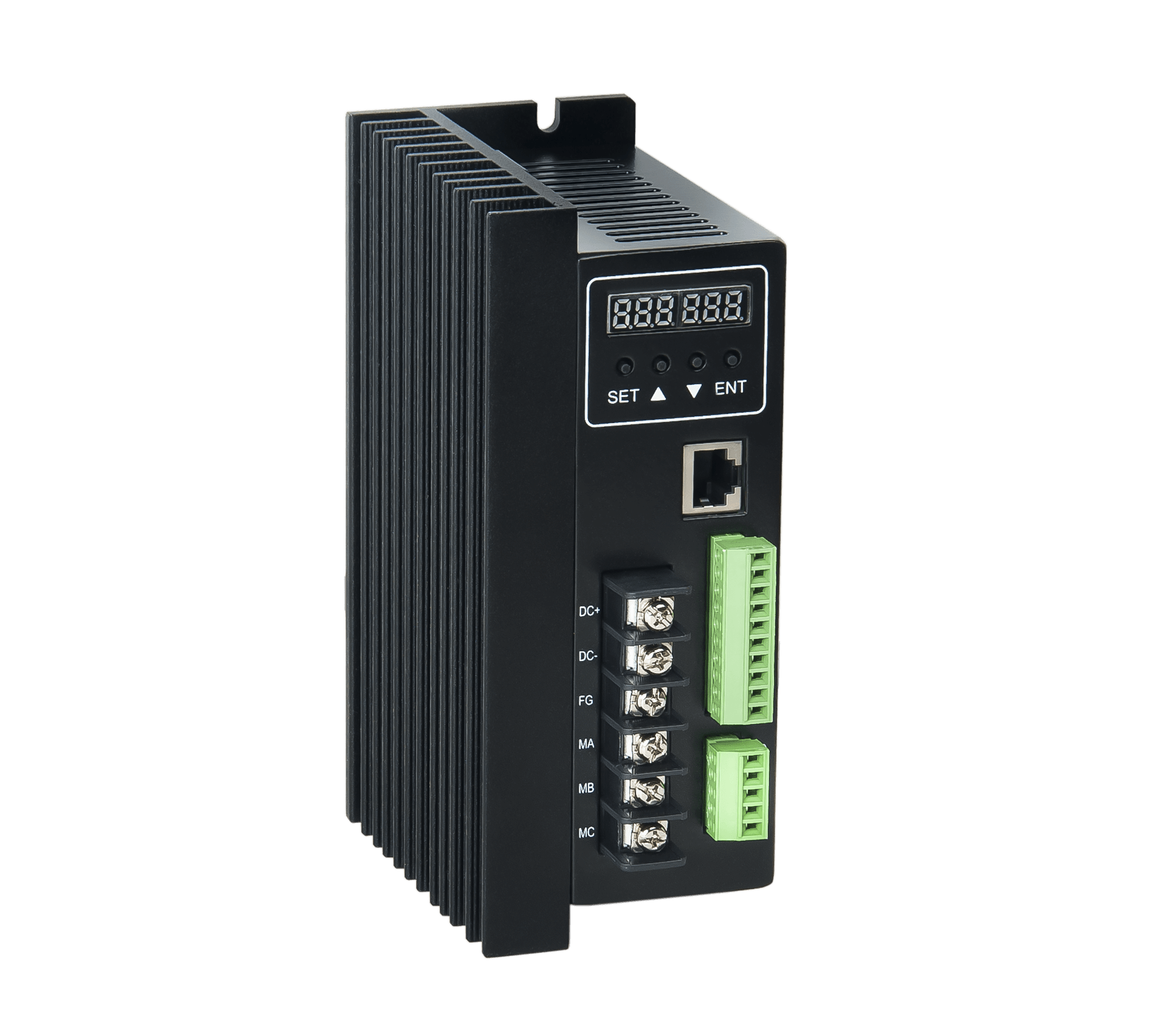
Iii. Driver interface:
Power and motor terminals
| serial number | name | explaination |
| 1 | DC+ | Positive pole of dc power supply |
| 2 | DC- | Dc power supply negative pole |
| 3 | FG | ground electrode |
| 4 | MA (U) | Brushless motor winding U phase (A) |
| 5 | MB (V) | Brushless motor winding V phase (B) |
| 6 | MC (W) | Brushless motor winding W phase (C) |
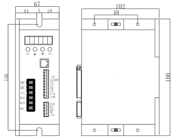
Hall sensor signal terminal
| serial number | name | explaination |
| 1 | GND | Hall sensor power supply negative pole |
| 2 | HA | Hall sensor A phase |
| 3 | HB | Hall sensor B phase |
| 4 | HC | Hall sensor C phase |
| 5 | +5V | Hall sensor power positive pole |
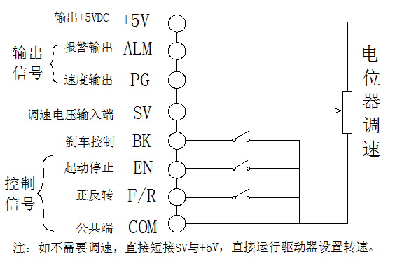
control interface
| serial number | name | explaination |
| 1 | reserved | Multisegment speed 1(with COM short) |
| 2 | reserved | Multisegment speed 2(with COM short) |
| 3 | +5V | + 5 v电源输出端口 |
| 4 | ALARM | Alarm output |
| 5 | PG | Speed signal output terminal |
| 6 | SV | Analog quantity (0~5VDC) signal input port |
| 7 | BR | Control signal brake end (corresponding to GND) |
| 8 | EN | Start and stop (corresponding to GND) |
| 9 | F/R | Forward and reverse control end (corresponding to GND) |
| 10 | COM | The public port |
4. Mounting size: 166*67*102mm
V. function and use
Speed way
The driver provides the following three speed regulation modes:
Panel speed adjustment: in panel mode, change the speed by +- adjustment.
External input speed: the two fixed end of an external potentiometer separately between the GND and + 5 v end of the drive, will adjust the termination in the SV side can use an external potentiometer (5 k to 100 k) speed regulation, can also be controlled by other units (such as PLC, SCM, etc.) input analog voltage to the SV to achieve speed control (relative to the GND), SV port to accept in the range of DC OV ~ + 5 v, corresponding to the motor speed of 0 ~ rated speed.Can also use external digital signal speed regulation: between SV and GND can be applied to the amplitude of 5V, frequency of 1KHz~2KHz pulse width digital signal (PWM) for speed regulation, motor speed by its duty cycle linear regulation.
Can also be in communication mode to set the motor speed instructions.
Motor operation/stop control (EN)
The on and off of the control terminal EN relative to GND can control the operation and stop of the motor.When the terminal is disconnected, the motor will stop.When the running/stopping end is used to control the motor to stop, the motor will stop naturally, and its motion law is related to the load inertia.
Motor forward/reverse control (F/R)
By controlling the on and off of terminal F/R and terminal GND, the running direction of the motor can be controlled.When F/R and terminal GND are not connected, the motor runs clockwise (facing the motor shaft), otherwise, the motor runs counterclockwise.
Brake stop
By controlling the on and off of terminal BK and terminal GND, the motor's braking and stopping can be controlled.The braking stop is faster than the natural stop, and the specific stop time is related to the load inertia of the user system.If there is no special stop requirement, natural stop should be adopted because the stop of braking has impact on electrical and machinery.
Motor speed signal output (PG)
The speed pulse output, the port for OC output (30 v / 10 ma Max), to get a signal with the power of the indirect 3 k Ω ~ 10 k Ω pull-up resistor.The terminal will output frequency and motor speed is proportional to the fixed pulse width (50uS) negative pulse string, motor per revolution of the output pulse number of 3 x N, N is the number of motor poles.Example: 12 pulses per revolution of a 2-pole, or quadrupole, motor.When the motor speed is 500 RPM, the output pulse of terminal PG is 6000.
Alarm output
Driver alarm output, the port is OC output (30V/10mA Max).To get a signal with the power of the indirect 3 k Ω ~ 10 k Ω pull-up resistor.When alarming, this terminal conducts with GND (low level), and at the same time, the driver stops working by itself and is in the alarming state.
Driver failure
When overvoltage or overcurrent occurs in the drive, the drive will enter the protection state, and the drive will automatically stop working, the motor will stop, and the drive will display the fault code. As long as the enabling end is reset (that is, EN is disconnected from GND) or the power is cut off, the drive can remove the alarm.In case of this fault, please check the motor wiring or clear the load.
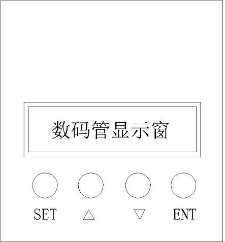
Vi. Display and keyboard operation
Note: "SET" : return key
"" : set parameters parameter value plus 1
Parameter value minus 1 when setting parameters
"ENT: ENTER" confirm key (call out system parameters)
The key position is shown in the figure above:
6.1 system parameter setting method:
1. The system parameter setting must be in the state when the motor is stopped, that is, when the motor is in the stop state in panel mode or in the enable disconnection state in external port mode. In the case of standby, press "ENTER";Will call up system parameters, and then press ENTER key, will call up the setting value of system parameters.
2. Press "train" or "polish" to the parameters you want to modify.If you do not want to change the "SET" key to jump out of the setting, back to standby state.
3. Press "ENTER" key again to see the parameter content.If you do not want to change the "SET" key to jump out of the setting, back to standby state.
4. Press "train" or "polish" to adjust the parameters.
5. Press "ENTER" to store parameters, and press SET to return to standby state.
Description: in the setting state, if no button is pressed for one minute, it will automatically jump to the speed display interface.
6.2 working mode:
There are two working modes of the driver, which can be set by the panel.Second is the external port working mode;Motor in accordance with the setting mode, digital tube display motor speed.In the panel work mode, press the SET key start, stop motor, long press and hold the delta, grand, reduce the motor speed, press ENTER to determine the motor speed.The motor runs at the set speed.
6.3 protection mode:
When the motor is abnormal during operation, the digital tube displays Err.
(1)Err--01 means the motor is blocked.
(2)Err--02 represents over current.
(3)Err--04 denotes hall fault.
(4)Err -- 05 means the motor is stalled and hall fault.
(5)Err--08 indicates input under-voltage.
(6)Err--10 denotes input overvoltage.
(7)Err -- 20 represents the peak current alarm.
(8)Err -- 40 indicates temperature alarm.
6.4 drive detailed parameter Settings:
| P00X Group: system operation parameters |
function code
| name
| range | unit | The factory set up | change |
| P000 | Control mode setting | 00 Closed loop control for external ports |
| 0 |
|
18 for the panel control mode and 485 communication control mode | External port control mode |
| P001 | Polar logarithmic setting | 1~255 | antipode | 2 | ○ |
| P002 | Rated speed setting | 1~65535 | RPM | 3000 | ○ |
Valid for external port mode |
| P003 | display format | 00:Speed display mode: |
| 0 | ○ |
|
|
|
|
| 01:PWM speed regulation mode: |
|
|
|
|
| 02:Segmented speed regulation mode: |
|
|
|
|
| 80:Current display mode: |
|
|
|
| P004 | pull-in torque | 1~255 |
| 16 | ○ |
| P005 | Non-inductive starting initial speed | 1~255 |
| 4 | ○ |
| P006 | Acceleration time setting | 1~255 | 0.1S | 0 | ○ |
| P007 | Deceleration time setting | 1~255 | 0.1S | 0 | ○ |
| P008 | Current Settings | 1~255 |
| 44 |
|
| P009 | Temperature alarm setting | 1~255 |
| 34 |
|
| P010 | Panel speed setting | 0~65535 | RPM | 2000 |
|
Only works for panel mode |
| P011 | brake | 0~1023 |
| 1023 |
|
| P012 | The site address | 0~250 |
| 1 |
|
| P013 | retain |
|
|
|
|
| P014 | Current display adjustment factor | 0~FF | hexadecimal | 3A |
|
| P015 | retain |
|
|
|
|
| P016 | Section speed regulation mode each speed regulation |
|
|
|
|
Vii. System usage:
Firstly, connect the connection line between the motor and the driver (motor winding line, hall signal line and power line), and the connection line must be strictly in accordance with the requirements. Unlike asynchronous motor, positive and negative rotation can not be realized by changing the connection line. Incorrect connection will lead to abnormal or non-normal operation of the motor, and display the fault code.
Motor when the motor winding line, hole lines connect the power cord and drivers, can run, potentiometer to set the minimum first, and then press start switch, potentiometer slightly increase motor, the motor should be run, such as the motor is not running, or shiver, and drives will display the corresponding fault code, the possibility of motor line phase sequence or hall wire sequence is wrong, please check the order of the brushless motor fuses, again until it can realize the normal movement of the motor, stop.
Viii. Communication:
The communication mode adopts standard Modbus protocol and conforms to national standard GB/T 19582.1 -- 2008.Using RS485 based double wire serial link communication, physical interface using RJ45 network line interface terminal, serial connection is very convenient.Transmission mode RTU, validation mode CRC, CRC start word FFFFH.Data mode 8 bit asynchronous serial, 1 stop bit, no effect bit, communication speed of 9600bps, now only one speed.
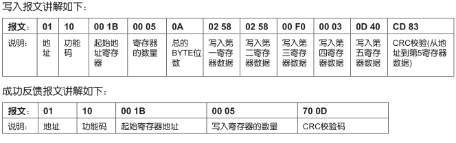
ModenBus Communication control register definition
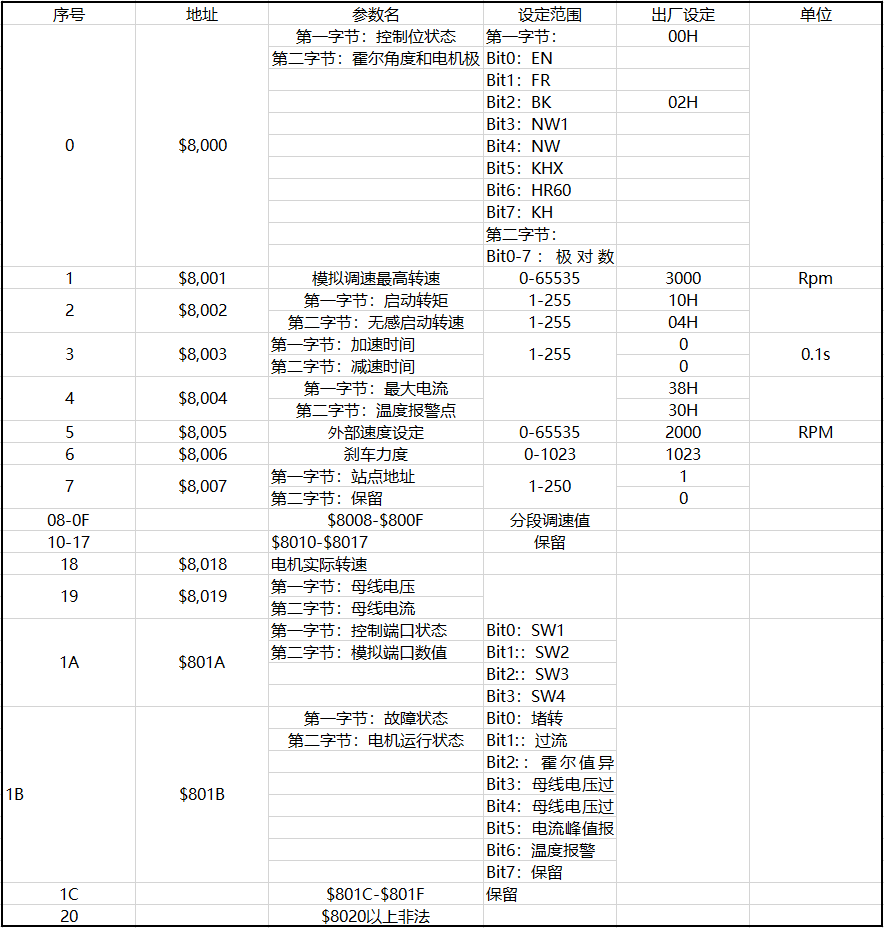
The address 8000H -- 8017H is the read-write register
Address 8018H - 801FH is a read-only register other addresses are illegal
8000: first byte: EN: at NW=0, 0: external EN low effective 1: external EN high effective
At NW=1, 0: EN is invalid and 1: EN is valid
FR: at NW=0, 0: external FR low effective 1: external FR high effective
At NW=1, 0: FR is invalid and 1: FR is valid
BK: at NW=0, 0: external BK is low effective 1: external BK is high effective
At NW=1, 0: BK is invalid 1: BK is valid
NW1:0: external effective control end (EN,FR,BK) 1: internal effective
NW: 0: external effective speed regulation value, 1: internal effective speed regulation value
KHX: in the mode of open loop with inductance, whether the alarm is blocked or not 0: it can be blocked or turned; 1: no alarm
HR60:0:12 0 ° control 1:6 0 ° hall hall (temporarily does not support)
KH: 0: closed loop control 1: open loop control
illustrate:
1. Write 1500 RPM: 01 06 80 05 DC 05 28 C8
2. Write 2 pairs of EN startup: 01 06 80 00 19 02 2A 5B
3. Write EN stop: 01 06 80 00 02 2B CB
4. Write brake: 01 06 80 00 1D 02 28 9B
5. Inquire motor fault status: 01 03 80 1b 01 DD CD
6. 01 06 80 00 19 02 2A 5B EN start 2 pairs
7. 01 06 80 05 D0 07 AC 09 write 2000
01 06 80 05 E8 03 BE 0A write 1000
9. 01 06 80 00 02 2B CB EN stop
01 06 80 00 19 01 6A 5A 1 pair of en start
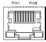
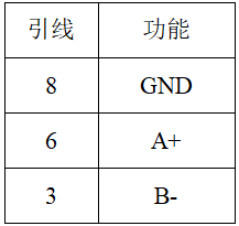
九、通讯接线方法:
RS-485通讯可以通过驱动器RJ45连接器使用网线进行通讯。
RJ45连接器的引脚定义如下: